Brainstorming a Modern Retro Console, Part 2
In which the author channels his inner mad scientist and lays out ideas for a modern, retro-built video game console, continuing with part 2: the Posit16-based rasterizer.
By: TheHans255
4/8/2024
A few weeks ago, the work I've been doing with the MOS 6502 gave me some inspiration for a modern retro console design that uses the processor, much like the NES and other consoles of the 1980s. I thought: if I wanted to build something that would carry the same design ethos as those consoles, with retro processors and bespoke graphics and audio hardware, yet had the benefit of modern technology and wanted to build something that made more unique and capable games than those original consoles could, what would I build?
This post is the second of a four-part series. If you haven't read part 1, about the CPU array for this system, I highly recommend doing so first. This part will cover the GPU for this console concept, part 3 will cover the cartridge interface, and part 4, will cover the other parts.
(And again, a disclaimer: I have not built or tested any of this. All of this comes from my knowledge of the 6502 and other electrical engineering that I have picked up passively over the years, and while I believe that these designs would work to the best of my knowledge, I provide no warranty on any of these designs' effectiveness or their safety in mission critical systems. If I ever get around to physically building these designs, I will update this article with my results.)
To Begin: Communicating With The GPU
The reality is, for consoles like this, we have a lot of choices for what our GPU would look like. We could go with one of several direct framebuffer construction systems, such as the CGA or EGA standards or another graphics format, or tile/sprite based systems like those found on the NES or the MSX line. Regardless of what we choose, we will need to establish a communications system with the GPU, and with our 65C02 system, three options come to mind:
- Memory-mapped IO serial ports - the CPU sends data to the GPU by repeatedly writing to one or a handful of addresses. This is the least demanding on the CPU's memory range but also the slowest, as each byte must be loaded into the 65C02's registers and stored into the communications address individually, wasting multiple cycles per byte.
- Video RAM mapped directly into the central memory - the GPU would take a turn on the Round Robin access model and use its turn with the memory to access the parts it needs to draw. This provides the most flexibility with memory access and also the best speed for the CPU, but is only viable if the video RAM only takes up a small portion of the total addressable space (such as in a tile-based rendering system).
- Direct memory access (DMA) from central memory - the GPU maintains its own state away from the central memory, but still accesses the central memory to extract commands from arbitrary locations given by the CPU. This provides a good compromise between the two modes, offering flexiblity on where graphics commands are stored in central memory (if they are stored there at all at any given time), though still incurring the latency of the CPU having to construct the graphics information and the GPU then having to pick it up.
For our system, we will offer the first and third methods, making a DMA transfer equivalent to sending the same data over the serial communications address. It should be noted that some DMA mechanisms, such as the one found in the Game Boy Advance, stop the processor while the DMA transfer occurs, while with our Round Robin central memory access system, this is not needed.
Now, Introducing Our Monstrous Creation
Of course, I wouldn't devote an entire post to our modern retro console design's GPU if we were just going to slap a boring old CGA framebuffer on it. I think it would be fun to challenge ourselves to do something a bit more ... interesting. Insane. Monstrous even.
We're gonna try to build a 3D polygonal rasterizer! Complete with triangles and wireframes and a depth buffer and bitmap textures and lighting! And probably vertex transformations if we can fit those in!
Of course, there are some limitations we have to respect here. Chief among them is the fact that whatever graphics chip we build, it is going to be fed by a handful of 14 MHz 8-bit CPUs, which can only move so much data per second. Plus, we want to stay in general keeping with the design ethos of the old 6502-based systems and create something that respects those systems' limitations while still providing powerful options for programmers (and also something that can still be relatively budget friendly).
Hence, we are going to subject ourselves to the following limitations:
- To keep textures and frame buffers small, the entire screen will be limited to 16 colors. We would allow the software to choose those colors from a wide palette (much like how the palette-based systems of the NES and the like worked), but only allowing a few colors on the screen at a time means that 2 full pixels can be stored per byte.
- The screen resolution will only be 256x128, which creates a 16 KiB widescreen image.
- Vertices and UV coordinates would be limited to 16-bit coordinates. To improve the dynamic range and precision of these values, we would make use of posits, a relatively new floating point format that makes use of variable-sized exponents, thus offering more precision in the ranges where most of our work will be done.
Wait, What is a Rasterizer?
There are a handful of techniques for rendering 3D models and scenes. A rasterizer is one such technique that takes lines and shapes (such as polygons used to construct a 3D model) and immediately calculates which pixels correspond to them, drawing them to the screen. Because of how fast this technique is, it is the standard technique for real-time 3D rendering in video games, in comparison to path tracing which can be much more physically accurate but requires far more computation.
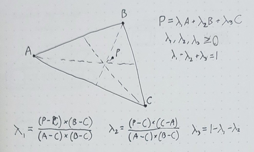
Practically, most rasterizers operate on triangles, which are sent to the rasterizer as sets of 3 points - since all other polygons can be made out of triangles, it makes sense to only build hardware for rendering triangles. And rendering triangles is easy: by making use of barycentric coordinates, you can not only tell exactly which pixels on screen are inside the triangle, but also have a good idea of where inside the triangle those points are, allowing you to interpolate values attached to the other coordinates.
For instance, you might have a data structure for your triangle points (or "vertices") that looks like this:
struct Vertex {
  float3 position : POSITION; // 3D position
  float2 uv : TEXCOORD0; // texture coordinate
}
In addition to the position field, the triangle vertex also contains a uv field,
which tells the rasterizer which specific part of a reference image (or texture)
is supposed to correspond to that point (for instance, each corner of a rectangular
sign would have its uv coordinate set to the matching corner of the sign). When
the triangle is later rasterized and all of the position values are smoothly
interpolated across all of the pixels being drawn, the uv coordinates are interpolated
as well, causing the texture to appear correctly across the whole surface of
the triangle. This can also be demonstrated with other factors -
if your vertices have just flat colors on them, for instance, the rasterizer would draw
a smooth gradient from one vertex to the others.
What are Posits?
Let's get the weirdest one out of the way first: what are posits? A posit, or an unum as they are sometimes called, is a format for floating point numbers proposed by computer scientist John Gustafson, positioned as an alternative to the ubiquitous IEEE 754 standard. The main genius of posits, other than taking out a lot of the exceptional cases that trip up IEEE 754 users (for instance, in Posit land, there is only one NaN, which is equal to itself and is only used for errors), is that posits use a variable number of bits to encode the exponent part when the exponent is close to zero (i.e. when the number is close to 1 or -1). They also lean heavily on the strengths of twos-complement signed integers, such that no extra instructions need to be written to compare or sort them.
To demonstrate how this works, we will take two random patterns of 16 bits and show how they compile into posits:
Example 1: 1001_0111_0100_0100 (two's complement integer: -26,812)

Step 1: Sign bit (first bit, S) is 1, so convert to two's complement:

   0110_1000_1011_1100

Step 2: Split into sign, regime, exponent, and mantissa:

   0_110_10_0010111100

Step 3: Count bits to determine value of the regime R:

   - The regime is a string of identical bits followed by the opposite bit -
     here, two 1s followed by a 0. In the case of k leading 1s, R = k - 1 = 1.

Step 4: Get the exponent E from the next two bits:

   - Here, the bits are 10, giving E = 2

Step 5: Get the mantissa F from the remaining bits:

   - Here, the bits are 0010111100, so F = 1.0010111100 (in fractional binary)

Step 6: Put it all together to get the value

   - The final value = (-1)^S * 2^(4 * R + E) * F = -1.0010111100 * 2^6
Example 2: 1101_1011_0100_0101 (two's complement integer: -9,403)

Step 1: Sign bit (first bit, S) is 1, so convert to two's complement:

   0010_0100_1011_1011

Step 2: Split into sign, regime, exponent, and mantissa:

   0_01_00_10010111011

Step 3: Count bits to determine value of the regime R:

   - The regime is a string of identical bits followed by the opposite bit -
     here, one 0 followed by a 1. In the case of k leading 0s, R = -k = -1.

Step 4: Get the exponent E from the next two bits:

   - Here, the bits are 00, giving E = 0

Step 5: Get the mantissa F from the remaining bits:

   - Here, the bits are 10010111011, so F = 1.10010111011 (in fractional binary)

Step 6: Put it all together to get the value

   - The final value = (-1)^S * 2^(4 * R + E) * F = -1.10010111011 * 2^(-4)
We can make several observations here:
- In both of these numbers, the sign bit indicated that the rest of the number was encoded as its two's complement, rather than as a simple flag. This means that flipping the sign of a posit is the same as flipping the sign of an integer.
- The second posit's exponent was closer to 0, and as such took only 4 bytes to encode instead of 5. There was thus one extra bit of precision available.
- Between both the two's complement integer and the posit, the first bit pattern was numerically smaller than the second bit pattern.
Since the introduction of the posit, several studies have been performed on FPGA implementations and have shown that posits can perform comparably to floats of similar size and still function correctly with fewer total bits. This is highly promising for our concept GPU, since it means that we can accept smaller coordinates while still getting high-quality results. Specifically, 16-bit posits have eleven bits of precision in the range of [-24, 24) (with more effective precision in the middle of that range), which is one more bit of precision than a half-precision IEEE 754 float.
Hence, in our GPU, we will accept 16-bit posits for all coordinates, and use 8-bit posits for values that can accept the reduced precision.
In addition, for operations that don't make as much sense to put through the GPU, such as preparing transformation matrices or doing simple collision checks, each 65C02 will have access to a coprocessor that can perform arithmetic on 16-bit posits. These will be accessed through hardware registers at the top of each processor's private memory.
For more footnotes on posits, see Appendix A below.
Now How About Them Colors?
Like many game and computer systems of the 1980s, our modern retro console will have a very limited color palette, with only 16 colors available. This allows textures to be stored with 2 bytes per pixel, causing, for instance, our full-screen 256x128 frame buffer to take about 16 KiB of memory.
However, in order to enhance the artistic breadth of the console, the console will give developers the freedom to choose exactly what those 16 colors are. Over the years, community palette collections, such as the Lospec Palette List, have demonstrated that artists can still create great pixel art with interesting color choices and tones, even when limiting themselves to 16, 8, 4, or even 2 colors, just as long as the display hardware is still capable of drawing 16-bit or 32-bit color, or colors of even higher bit depth. Hardware that can only display a few colors tends to emphasize having a high range of hues, with only some emphasis on saturation and lightness, or lean the exact opposite direction with a single-tone, grayscale/sepia palette. A user created palette can play with these parameters, such as by choosing multiple shades of a base color and an accent color, or using a greyscale palette where the brightest and darkest colors are more muted, or have 3 or 4 hues that are not necessarily equilateral on the color wheel.
To implement this, we would allow the user to specify a global color palette, mapping each of the 16 colors to a 15-bit color (with each color channel being 5 bits and the last bit indicating whether the color should instead be transparent). All data would be stored as the indexed color and would be translated into the chosen final color when the frame buffer is drawn to the screen.
This choice, of course, does introduce some caveats:
- Using fully indexed color means that if triangle vertices have built-in, flat colors, then colors cannot be interpolated using Barycentric coordinates. This isn't a huge problem, since color gradients can be expressed manually through textures, but if that's too much, it might be useful to introduce an ordered dithering method to simulate color interpolation.
- Also, since there are only 16 colors in the frame buffer, if we want to introduce a depth buffer, we would likely need to make it far larger than the screen, since 16 levels of precision is probably not enough. Of course, there will usually only be one depth buffer in VRAM while there might be several texture buffers.
How About Lighting?
With only 16 colors, we can actually do something quite interesting with a possible built-in lighting engine. Having indexed colors means that we can't do any direct color-value math on our colors to determine how they should be shaded, but having only 16 colors means that it becomes economical to do an exhaustive lookup table on how each color should be transformed based on its exposure to incoming light. This allows us to not only have a highly customizable lighting system, with things like toon shading and threshold lighting, but also palette-swapping and colored lighting at the same time (as long as all lights considered in the scene are the same color and intensity).
Specifically, developers could set a lighting table for each incoming color, mapping it to one of 8 colors based on how intensely it is lit. For instance, a normal daylight scene with a linear grayscale palette might have a pattern like this:
0: 00000000
1: 11110000
2: 22211000
3: 33221100
// ... and so on
while at night, it may be changed to this:
0: 00000000
1: 00000000
2: 11000000
3: 11110000
4: 22211100
// ... and so on
A palette swap with flat shading might be created like this:
0: 88888888
1: 99999999
2: AAAAAAAA
// ...
Or you might mix it with some lighting like this:
0: 88885555
1: 99996666
2: AAAA7777
// ...
As for the lighting itself, I estimate that you could probably get away with a simple directional light for most scenes, specifying the direction as a 3D vector. Indoor scenes might benefit from having two point lights, both of which are stored as 3D positions.
Other Ideas: How Would We Put It Together?
There are quite a few other decisions about the implementation of this renderer that are more up in the air, which would likely depend on further research and field tests with what the CPUs could provide and how expensive the systems become.
- One major decision hinges around using a fixed-function pipeline (where the CPU simply sends parameterized commands, much like the PSX and earlier versions of OpenGL and DirectX), and a programmable shader pipeline (where the CPU first sends code to the GPU to instruct it on how to subsequently interpret its vertex and color data).
- There's also whether or not to include a depth buffer. I think it's rather obvious that we should at least include the Z coordinate in all vertices that we send to the GPU, so that it can perform an appropriate perspective divide and avoid the texture warping problem that the first PlayStation had. However, it might be a valid choice to either save memory and require the user to pre-sort their vertices back to front (which might be OK for our system to do, since Posit16 vertices can be sorted by integer hardware and we are supporting multithreading), or to add additional VRAM and do the sorting for the processor.
- It also wasn't until the sixth console generation that we started getting vertex transformations on the GPU - earlier systems expected that the vertices had already been projected into screen space. Adding vertex transformations would require additional hardware in the GPU and additional parameters for the CPU to juggle, but would also allow the CPU to avoid having to modify vertex data and instead just send it to the GPU once to be cached in VRAM. (Though of course, this will also necessitate a depth buffer, since the CPU would have to sort the polygons by depth otherwise.)
A lot of these tests will likely hinge around trials of the system rendering example models and scenes, ranging from standard models such as Suzanne, the Utah teapot, and the Cornell Box, to famous objects in video games such as Princess Peach's Castle, to wholly original scenes. We would need to evaluate, under different models and design decisions, what kind of code our console would need to execute to render these demos and how much time and resources it has for other calculations.
That's it for Part 2. Head back to Part 1 for a more in-depth look at the CPU, or go ahead to Part 3 for a look at the cartridge system!
Appendix A: A Bit More About Posits
For academic interest, here are a few more details about exceptional cases for posits:
- Posits do have two special bit patterns that don't follow the sign/regime/exponent/mantissa rules: if all the bits are zero, the result is zero, and if the sign bit is 1 while all the other bits are zero (i.e. taking the two's complement doesn't do anything), the result is "Not a Real", which is simultaneously infinity, negative infinity, and NaN all at once. There is no positive/negative 0, no "subnormal" numbers that change the fraction bits, and only one NaN.
- The NaR value is used exclusively for errors - underflow rounds to zero, overflow rounds to the finite value of greatest magnitude.
- If the regime is long enough that there starts to not be enough room for the 2-bit exponent or even the expected opposite bit for the regime, the remaining bits are treated as zero. For instance, the value 0111_1111_1111_1111 will be rendered as 2-56, and 0111_1111_1111_1110 becomes 2-52. (This also means that a posit can safely have its precision extended simply by tagging additional 0 bits to the end)
- Posits are also associated with a structure called a quire, which is used to accurately add and multiply a bunch of posits together and basically amounts to a very large fixed-point number. Quires are primarily relevant in machine learning applications where a lot of exactly those transformations are happening.